Arete Logo Jpeg Sep 19

H 143, Gurunanak Market, Mehrauli – Badarpur Rd, Lal Kuan, New Delhi, Delhi 110044

Soil Resistivity Testing

  • Home
  • Soil Resistivity Testing

Resistivity Testing of Soil

Gel Earthing Electrode Manufacturers
sr 3 4
price img 1 4

Resistivity Testing of Soil Service,

Arete Powertech’s Resistivity Testing of Soil Service, where we delve into the very foundation of electrical safety to ensure your systems are grounded in reliability and resilience. With a legacy from 2008, Arete Powertech has been a pioneering force in Electrical Safety and energy-efficient solutions, setting industry standards and empowering clients with cutting-edge technologies.

Actual Quality Percentage Figure

Or an actual quality percentage figure (e.g., “99.9% reliability” for your earthing products

Understanding Resistivity Testing of Soil:

Resistivity Testing of Soil is a fundamental aspect of electrical safety, especially in industries where grounding systems are critical. It involves measuring the resistance of the soil to the flow of electric current, providing crucial insights into the effectiveness of earthing systems and their ability to dissipate fault currents safely.

Why Resistivity Testing of Soil Matters:

In the realm of electrical safety, understanding soil resistivity is paramount. The soil’s resistivity directly impacts the performance of grounding systems, affecting their ability to mitigate electrical hazards such as electric shock, equipment damage, and even the risk of fire.

Our Comprehensive Approach:

At Arete Powertech, we recognize that no two sites are the same. Our Soil Resistivity Testing service is tailored to meet the unique needs of each client, taking into account factors such as soil composition, moisture content, and environmental conditions.

State-of-the-Art Technology:

We leverage advanced equipment and methodologies to conduct precise soil resistivity measurements. From Wenner four-pin arrays to sophisticated digital analyzers, our arsenal of tools ensures accurate data collection and analysis, allowing us to offer informed recommendations for optimizing your grounding systems.

What is Resistivity Test of Soil and How is the Testing Done

Resistivity testing of soil is a method used to measure the resistance of a soil sample to the flow of electric current. This test is important in various fields, including electrical engineering, environmental science, and geotechnical engineering. It helps in determining the suitability of the soil for grounding systems, evaluating the corrosion potential of buried structures, and designing effective grounding systems for electrical installations.

Here’s how the testing is typically done:

Preparation: Before conducting the test, the testing area needs to be prepared. This involves clearing the surface of any debris, vegetation, or obstructions that could interfere with the measurements.

Selection of Test Locations: Test locations are selected based on the area of interest. Typically, a grid pattern is established over the site, and measurements are taken at various points within this grid to provide a representative sample of the soil’s resistivity.

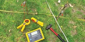
Installation of Electrodes: Four electrodes are used for the test:
Current Electrodes: Two electrodes are placed in the ground at a fixed distance apart, typically 1 meter or more, to inject a known current into the soil.
Potential Electrodes: Two additional electrodes are placed in the ground at a fixed distance from the current electrodes to measure the voltage drop across the soil.

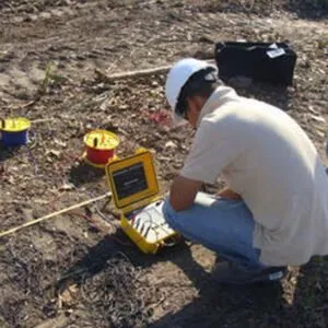
Measurement: A known current is passed through the soil using the current electrodes, and the resulting voltage drop is measured using the potential electrodes. The resistance of the soil is calculated using Ohm’s Law (R = V/I), where R is the resistance, V is the voltage drop, and I is the current.

Data Collection: Measurements are taken at each test location, and the resistivity values are recorded. Multiple measurements may be taken at each location to ensure accuracy and consistency.

Data Analysis: Once all measurements are collected, the data is analyzed to determine the variation in soil resistivity across the site. This information is used for various engineering purposes, such as designing grounding systems, assessing corrosion risks, or evaluating soil contamination.

Interpretation: The results of the soil resistivity test are interpreted in the context of the specific application or project requirements. Engineers use these results to make informed decisions regarding the design and implementation of electrical systems, environmental remediation plans, or other projects where soil resistivity is a critical factor.

Why Testing Resistivity of Soil is Important ?

Resistivity Testing of soil is important for several reasons:

Grounding System Design: Soil resistivity data is crucial for designing effective grounding systems for electrical installations. A low-resistivity soil can dissipate electrical charges more efficiently, reducing the risk of electric shocks and equipment damage.

Corrosion Risk Assessment: Soil resistivity affects the corrosion rate of buried metal structures, such as pipelines and underground tanks. High resistivity soils tend to promote higher corrosion rates, while low resistivity soils are less corrosive. By understanding soil resistivity, engineers can assess and mitigate corrosion risks.

Electrical Safety: In electrical installations, proper grounding is essential for ensuring the safety of personnel and equipment. Testing soil resistivity helps determine the adequacy of the grounding system and ensures compliance with safety standards and regulations.

Lightning Protection: Soil resistivity data is used in designing lightning protection systems for structures and facilities. A thorough understanding of soil resistivity helps engineers optimize the design of grounding electrodes to safely dissipate lightning strikes into the ground.

Subsurface Exploration: Soil resistivity testing is also used in geotechnical engineering and environmental studies to characterize subsurface soil properties. Variations in soil resistivity can indicate changes in soil composition, moisture content, and contamination levels, providing valuable information for site investigations and construction projects.

Soil resistivity significantly impacts the design of an earthing system and is the primary factor determining the system’s earth resistance. Therefore, prior to designing and installing a new grounding system, it’s essential to test the soil’s resistivity at the intended location.

Type of Soil or Water

Sea water

Clay

Ground well & spring water

Clay & sand mixtures

Shale, slates, sandstone etc.

Peat, loam & mud

Lake & brook water

Sand

Moraine gravel

Ridge gravel

Solid granite

Ice

Typical Resistivity Ωm

2

40

50

100

120

150

250

2000

3000

15000

25000

10000

Usual Limit Ωm

0.1 to 10

8 to 70

10 to 150

4 to 300

10 to 100

5 to 250

100 to 400

200 to 3000

40 to 10000

3000 to 30000

10000 to 50000

10000 to 100000

The Arete Advantage:

Expertise: With over a decade of experience in the field, our team of certified engineers and technicians possesses the knowledge and expertise to handle soil resistivity testing projects of any scale or complexity.

Precision and Accuracy: We adhere to stringent quality standards and best practices to deliver reliable and accurate results, empowering our clients with actionable insights to enhance the performance and safety of their electrical systems.

Customized Solutions: Our approach is client-centric, focusing on understanding your specific requirements and tailoring our services to address your unique challenges and objectives.

Compliance and Reliability: We are committed to upholding international standards and regulations, ensuring that our soil resistivity testing services comply with industry norms and guidelines.

Beyond Testing: Empowering Safety and Reliability

At Arete Powertech, our commitment extends beyond soil resistivity testing. We are dedicated to partnering with our clients to safeguard their operations, enhance reliability, and mitigate risks associated with electrical systems.

WHAT WE OFFER

Professional Services

sr 1 1 1

G.I. Earthing Electrode

Hot dip galvanized fir long life. Maintenance free with 15+ year life. Easy installation. Sizes: 1 meter to 3 meters. Diameter: 20 mm to 100 mm

sr 1 2 1

Copper Earthing Electrode

Corrosion free with 25+ years life Advanced engineering. Excellent thermal and electrical conductivity Sizes: 1 meter to 3 meters. Diameter: 20 mm to 80 mm

sr 1 3 1

Copper Bonded Earthing Electrode & ROD

Cost effective vis a vis maintenance free. Copper coating 250 micron comes with 20+ year warranty. Size: 1 meter to 3 meters. Diameter: 14 mm to 80 mm. UL approved earthing also available.

sr 1 4 1

Exothermic Welding

Superior electrical conductivity. Does not Corrode or degrade wit time. Able to withstand repeated electrical discharges. Never increase its resistance.

sr 1 5 1

Lighting Arrester

ESE Type. range 45 meter to 107 meter radius. Designed and tested as per NFC17-102 and UNE-21 186. Stainless steel design. Life 20+ year Available in three models to suit specific site requirements

price 1 2 1

Rooftop Solar Power Plant

Get rid of dependence form eternal suppliers. Combine different energy source Grid, DG Set. Tailor - made expandable modules system. Install a hassle - free best rooftop solar power plants. 5KW to 50KW - ON - Gird, Off - Grid & Hybrid.